LB / LONDON BELOWTHE CITY BENEATH THE CITY
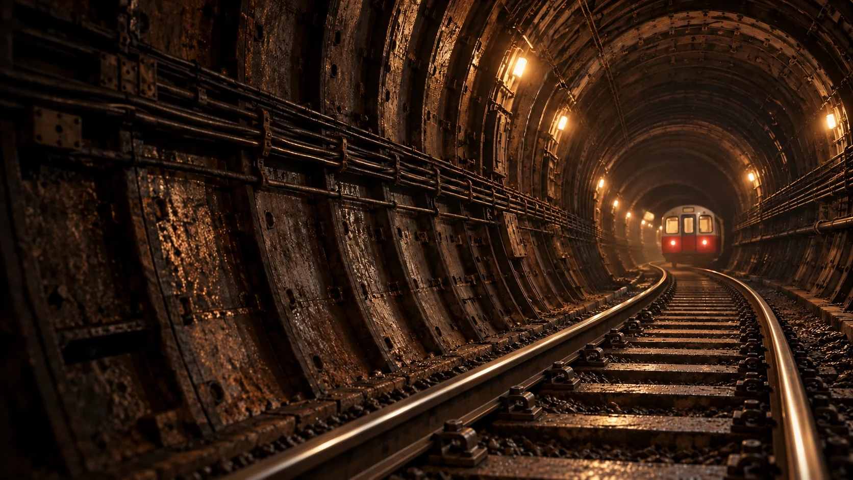
An illustrated deep Tube tunnel, its rails curving towards a red-fronted train under warm work lights.

A JOURNEY THROUGH HEAT, CLAY & WATER

London
Below.

You know the feeling.
The platform is warm. The train is warmer.
The city holds on to its heat.

Begin the descent
A SCHEMATIC SLICE OF LONDONLayers exaggerated. Depths vary. Not to scale.
Shallow gravelsLondon Clay + tunnelsLower Palaeogene strataChalk aquifer

London,
in layers.

Explore a layer

Hover a layer to learn more.Tap a layer to learn more.

London, opened into the groundA schematic geological cutaway shows a city and river above shallow gravel, paired railway tunnels bored in London Clay, varied lower Palaeogene strata, and pale Chalk. Blue traces follow fractures in the Chalk. Layers vary locally; this illustration is vertically exaggerated and not to scale.

Where the
heat goes.

Trains are the main heat source. Traction, braking and equipment release energy.

Adjust heat input
Moderate
Less heatMore heat

Conceptual heat flow. No temperatures predicted.

London, opened into the groundA schematic geological cutaway shows a city and river above shallow gravel, paired railway tunnels bored in London Clay, varied lower Palaeogene strata, and pale Chalk. Blue traces follow fractures in the Chalk. Layers vary locally; this illustration is vertically exaggerated and not to scale.
Follow heat from a train into tunnel air and the groundA conceptual front-on cross-section through a railway tunnel in London Clay. The train sits inside the lining, with the ground around it. Copper arrows show heat moving from the railway into the air, and between the air, lining and ground. Ventilation can carry some heat away along the tunnel. The lining and ground absorb and release heat over time. These arrows show relationships, not quantities, temperature or a site-specific tunnel design.Lining + groundTunnel airTrain
Conceptual heat-transfer cross-section. Use the lesson controls to follow the train, tunnel air and surrounding ground.

Within
the rock.

Groundwater moves through fractures in the Chalk.

Follow the water
StartFollow the fracture
London, opened into the groundA schematic geological cutaway shows a city and river above shallow gravel, paired railway tunnels bored in London Clay, varied lower Palaeogene strata, and pale Chalk. Blue traces follow fractures in the Chalk. Layers vary locally; this illustration is vertically exaggerated and not to scale.
Water follows fractures through solid ChalkA conceptual magnified view of six solid pieces of Chalk. Narrow, irregular blue fractures separate the pale rock. A connected route follows one fracture and turns into another. The movable dot traces this illustrative path. This is not a map, a depth or water-level view, or a prediction of groundwater velocity. No connection to a railway tunnel is shown.RockFracturesWaterConceptual path
Conceptual path through connected fractures in solid Chalk. The drawing does not describe a real borehole, flow rate or tunnel connection.

04 / DESIGN A WAY OUT

Make the
connection.

Cooling moves heat somewhere else. Choose a route. Then look inside it.

OPERATING EXAMPLE

From the Tube
to the neighbourhood.

Bunhill 2 recovers warmth from tunnel air. An electrically powered heat pump supplies a district-heating network.

Reuse needs customers, pipe routes and matching heat demand. The aquifer is separate.

Recovering heat from tunnel air for buildingsA fan draws warm tunnel air past a heat exchanger. An electrically powered heat pump raises the recovered heat's temperature, and a separate district-heating water circuit carries it to buildings. This scheme does not use groundwater.TUNNEL AIRHEAT PUMPDISTRICT HEATElectrical inputRecovered warmthHeat to buildingsReturn water
SITE-DEPENDENT APPROACH

Separate waters.
A shared exchanger.

An exchanger passes heat between two separate circuits. The groundwater and railway cooling water do not mix.

Yield, water chemistry, thermal plumes and permissions constrain the design. This is a potential arrangement.

A potential open-loop groundwater cooling arrangementA groundwater abstraction well and a return well connect to one side of a heat exchanger. A separate sealed railway cooling circuit connects to the other side. Heat passes through the exchanger but the waters do not mix. Wells, return-water heating and environmental permissions are site dependent.RAIL COOLING CIRCUITHEAT EXCHANGERAQUIFER · SITE DEPENDENTAbstraction wellReturn wellPumps need electricityGroundwater carries heat away
LOOK CLOSER

Follow the warm route out, and the cooler return.

CONCEPTUAL FLOWS · SCROLL OR SELECT A COMPONENT

05 / CHECK THE EVIDENCE

The idea.
The reality.

Three projects. Three different stages.

Victoria: water already entering the drainage systemA conceptual section shows local drainage water collected in a sump, pumped through one side of a heat exchanger and returned to drainage. A separate cooling circuit connects the exchanger to a cooling coil. Heat crosses the exchanger while the two water circuits remain separate. This is not a well into the Chalk aquifer.LOCAL DRAINAGEHEAT EXCHANGERCOOLING COILWater already entering the stationDrawn from drainageReturnedSeparate cooling circuitCONCEPTUAL SECTION · NO DEEP-CHALK WELL

COMPLETED TRIAL

Victoria’s drainage water

Water already entering the station drainage system supplied a cooling trial.

Recorded complete in April 2008. Continued operation is not established by that record.

Bunhill 2: tunnel air becomes useful heatA conceptual section shows a fan recovering warmth from Northern line tunnel air. An electrically powered heat pump raises the useful temperature and transfers heat to a separate water circuit serving neighbourhood buildings. No aquifer or groundwater circuit is shown because this is an air-source heat-recovery installation.TUNNEL AIRHEAT PUMPNEIGHBOURHOOD HEATVentilation airElectrical inputRecovered warmthHeat to buildingsReturn waterCONCEPTUAL SECTION · NO GROUNDWATER CIRCUIT

OPERATING INSTALLATION

Bunhill 2’s recovered heat

A local heat network uses warmth from Northern line tunnel air. The aquifer is not part of this scheme.

Holborn: a water-cooled panel follows the tunnel curveA conceptual close section shows a curved metal cooling panel inside a tunnel. Cold water cools the metal and a fan moves air past it. The drawing explains the mechanism, not an as-built installation. TfL trialled a demonstrator on a disused platform; the January 2026 status was a successful proof of concept with product design continuing.AIR MOVES PAST COOLED METALCURVED COOLING PANELCold waterFanCONCEPTUAL SECTION · DISUSED-PLATFORM TRIAL

PROOF OF CONCEPT

Holborn’s cooling panels

The Mayor reported successful trials in January 2026, with product design still in progress. A wider rollout is not established.